VTracer
Researcher: Sanford Pun | Supervisor: Chris Tsang | Published: 2020-11-01
VTracer is a utility to convert raster images into vector graphics. Try the Demo Web App.
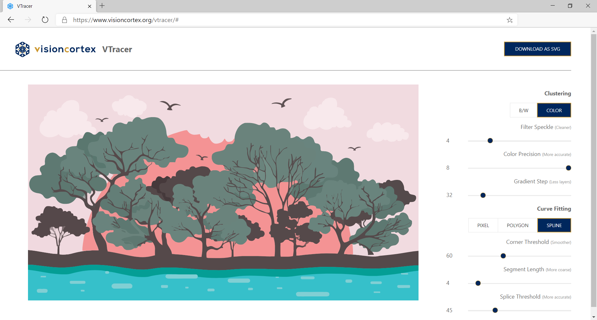
Graphic by sunshine-91 via Vecteezy
The input image is first clustered by Hierarchical Clustering, and each of the output clusters are traced into vector.
The algorithm of vector tracing involves 3 main stages:
Convert pixels into path
Simplify the path into polygon
Smoothen the polygon and approximate it with a curve-fitter
Path Walking
VTracer first obtains the raw paths of pixel clusters. A walker is used to trace the outlines of every cluster after building an image tree. The walker would combine consecutive steps in the same direction.

2 results of path-walking. Left: Naïve, Unoptimized walker. Right: Optimized walker.
Raw pixelated polygon
Path Simplification
Path simplification consists of 2 steps:
Remove staircases
Simplify by limiting subpath penalties
Staircase Removal
From the previous stage, we have obtained a path whose consecutive edges must have different directions, i.e. the shape is represented by the minimum number of edges with 100% fidelity. However, to represent slant lines and curves in raster graphics, “jaggies” (or pixel staircases) inevitably occur. In this step, we aim at removing these artifacts.
To replace a staircase with a straight line (hence “removing” it), one may adopt an outset (“additive”) or inset (“subtractive”) approach. Both approaches are justifiable in difference contexts, so the key is to maintain consistency in the same shape. In order to determine which points to keep, we make use of the signed area.

The signed area of a right triangle is a metric used to determine whether the vertices are arranged clockwise or anti-clockwise geometrically. With this information, we can determine which points to keep on the staircase.
For each point on the staircase, we calculate the signed area of the triangle formed by the previous point, the current point, and the next point on the path. The decision of whether the current point should be kept is then made by comparing the sign of the signed area and the clockwise-ness of the original path.

Two examples of signed area. If outset(inset) is chosen, B(B’) is kept and B’(B) is discarded.
Simplify by Limiting penalties
The path can be further simplified by evaluating the penalty from replacing a subpath with one long edge from the first to the last point.

Left: Path with wobbles. Right: Path approximated by red line, removing wobbles
Given a subpath, we would like to determine if a line drawn from the first point to the last can approximate the whole subpath with high fidelity. The idea is to make sure that all points in the subpath are close enough to the approximating line. To avoid all the complicated coordinate geometry, we can simply evaluate the areas of triangles formed by the first point, the last point, and each in-between point.
Let ΔABC be one such triangle, with A and C being the first and last points of the subpath respectively, and B being any in-between point. Let h and b be the height and the base (length of AC) respectively. VTracer models the penalty of ΔABC as  , as the area of ΔABC and b can be obtained by simple geometry. It is crucial for the penalty to be directly proportional to h and b.
Once the penalty is clearly defined, the procedure of simplification is straightforward. VTracer greedily extends a subpath until the maximum penalty along it exceeds a specific tolerance, then all edges in the subpath are replaced by one line from the first to the second last point (or equivalently, remove in-between points from the path). After the replacement, the same process is performed starting from the next point in the path. When the last subpath is extended to the last point in the whole path, the simplification stage concludes.

Path Smoothing
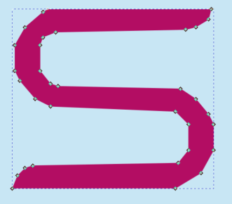
Sample Simplified 'S' Shape
What we have now is a simplified polygon with high fidelity. However, if we feed the path to the curve fitter as is, the curves will approximate the shape poorly. This is because the curves are underdetermined given the small number of points. In order to generate points that lie on our desired shape, subdivision smoothing is performed.
4-Point Scheme
VTracer adapts from the 4-Point Scheme subdivision algorithm, which is an interpolating smoothing method. The problem of the 4-Point Scheme is that all vertices would be smoothed into round corners, which, from our point of view, is a loss of fidelity.

4-Point Scheme performed on segment A₁A₂

If A2 is a corner, the 4-Point Scheme smooths it out iteratively.
Finding corners
To preserve corners, we first have to locate them. VTracer finds corners by checking the angle difference at each vertex. If the absolute angle difference exceeds a certain threshold, the vertex is considered to be a corner.

Angle difference from A to B is small => a is not a corner
Angle difference from B to C is large => b is a corner
Corner-Preserving 4-Point Scheme
In the original 4-Point Scheme, 2 adjacent points are always used to generate the new point for each segment. In our adapted version, we do not take the adjacent point for corners, but instead we take the corners themselves. For segments whose points are both corners, we simply ignore them.

Since A₂ is a corner, the smoothing procedure does not take the adjacent point as B₂. As a result, the corner will be (approximately) preserved after smoothing, even after iterations.
VTracer applies a threshold on the length of each segment during subdivision smoothing, so that the result will not be over-dense. This threshold should be decided carefully (mainly based on the resolution of image), otherwise the resulting path will be a poor approximation.
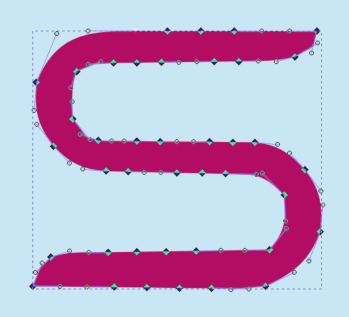
Shown below are examples smoothed with no iteration:

Length Thresholds 3.5/5.0/7.5
Introducing iterations, you can see more points are generated by subdivision:

Iterations 0/1/2
VTracer's implementation defaults to 10 iterations, and exit early when no further smoothing can be done on the path.
Curve Fitting
The path is now populated with nicely positioned and sufficiently dense points that faithfully represent our desired shape. Before feeding it to a (Bezier) curve-fitter, VTracer determines where to cut curves (splice points).
Finding Splice Points
To define a splice point, we make use of the signed angle differences. Interpreting each edge along the path as vectors, we can define the signed angle difference from edge eᵢ to eᵢ₊₁ as the 2D angle of rotation θ ∊ (-π, π] required to rotate eᵢ to the same direction as eᵢ₊₁ (assume positive θ in clockwise direction).
It is sufficient for a vertex to be a splice point if it passes one of two tests: point of inflection testand angle displacement test.
Points of inflection can be found by tracking the signs of angle differences along the path. When the concavity of the path changes at a certain point, the sign of the signed angle difference also changes at that point.

As the sign of angle difference changes at point P, P is a point of inflection and hence a splice point.
Therefore, we cut (A..B) into (A..P) and (P..B).
Angle displacement at a point is defined as the signed angle differences accumulated from the previous splice point (exclusive) to the current point (inclusive). If the absolute value of angle displacement at a certain point exceeds a specific threshold, that point is a splice point. The smaller the threshold, the more curves are cut, and the resulting spline is more accurate.

Angle Displacements shown along a path.
Once all splice points are found, VTracer feeds all subpaths between every consecutive pair of splice points into the curve-fitter.
If the smoothed path from the previous step is fed into the curve-fitter, we get a spline like the following:
Final output
vs Potrace
Fidelity
Potrace is a popular bitmap tracing tool that also transforms bitmaps into vector graphics. Being able to produce high-quality output for low-resolution images, Potrace traces images by finding global optimal under certain assumptions. VTracer favours fidelity over simplification. Potrace and VTracer produce different results especially on small objects.

Illustration of how assumptions affect tracing.
Left: Original input.
Middle: Possible shape interpretation with the assumption that ambiguous “corners” in the original input are sharp corners.
Right: Possible shape interpretation with no assumptions: “corners” in the original image are represented by curves or round corners.
Efficiency
Potrace finds the global optimal way of tracing a shape, meaning it approximates parts using information from the entire shape, which leads to performance issues in high-resolution images. On the other hand, VTracer runs a linear algorithm on each cluster and has lower CPU and memory usage. In fact, we regularly use VTracer to process high resolution scans at 10 megapixels.
vs Adobe Illustrator
Comparing to Adobe Illustrator's Live Trace, VTracer's output is much more compact thanks to a stacking strategy. VTracer's preprocessing stage utilizes Vision Cortex's image tree algorithm and never produces shapes with holes.